How we controls the AC
Developed over 30 years, iZone’s control strategies are designed to deliver optimal temperature control, energy efficiency and cost-effectiveness.
The various system control strategies are outlined below, each tailored to maximise comfort while minimising running costs.
Zone Damper Control
The zone dampers function in a standalone control system, operating independently as outlined below:
Basic Zone Operation – Open/Close Function
The simplest form of zone control is the basic open/close operation. As the name suggests, when a zone is opened, the damper drives to its maximum (MAX) open position. When closed, it moves to its minimum (MIN) closed position.
If the MAX setting is configured to 100%, the damper will open fully until the actuator motor triggers the MAX microswitch, which then cuts power to the motor. Similarly, if the MIN setting is 0%, the damper will close fully until the MIN microswitch is engaged, cutting power to the motor.
Damper Initialisation and Calibration on System Reset
When the iZone system is reset or power is cycled to the C225 module, all zone dampers will cycle fully open and fully closed several times. This process calibrates each damper by recording the time (in milliseconds) it takes to reach both end positions.
These timing values are then used to accurately position the dampers at partial openings-such as 75% open or 25% closed. For further details, refer to the Damper Timing section.
Damper Positioning and Airflow Control
To achieve different airflow percentages, the dampers operate for varying lengths of time. These percentages are calculated based on the estimated airflow performance of the damper, not the physical position of the damper blade.
As a result, the motor may run for longer or shorter durations to produce a similar change in airflow, depending on where the damper blade is along its operating curve. This is due to the non-linear relationship between damper position and actual airflow.
The iZone system uses the fully open and fully closed microswitches as calibration and reference points to ensure accurate positioning of each damper.
Air Balance Control
The iZone system includes a technician-level feature that allows balancing of both MAX and MIN airflow settings. These balancing adjustments operate independently from the Zone Air Flow MAX and MIN controls available to end users in the GUI.
For example, if the technician sets the Balance MAX to 75%, the end user can still adjust the Zone Air Flow anywhere between 0% and 100%. However, at 100% user setting, the actual damper opening will be limited to 75% based on the technician’s balance setting, without affecting the user’s control range.
Zone Temperature Control
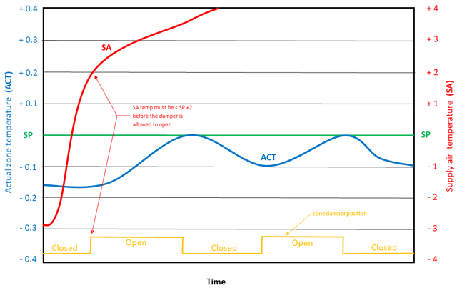
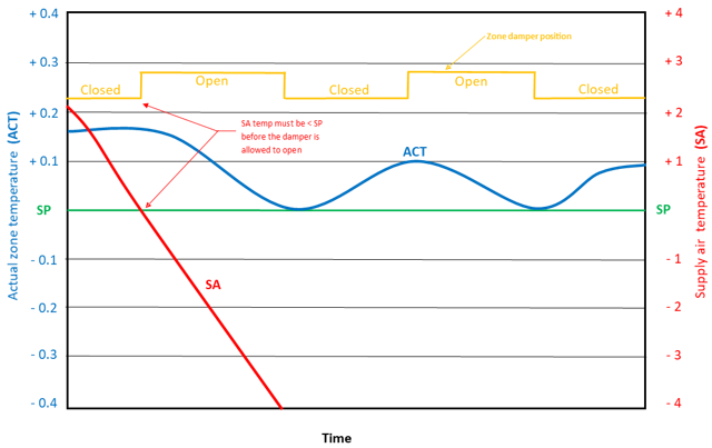
Zone temperature control requires each zone to be set to "Climate" mode and utilizes iZone wall sensors to modulate the zone dampers in order to maintain the desired setpoint. A key component in this control strategy is the supply air sensor (CDTS), which plays a critical role by reversing damper operation during heating mode. This helps prevent hot or cold air from being blown into a zone when the system initially starts.
The zone temperature control strategies rely on the following parameters for effective regulation:
- Zone Set Point (SP): As selected by the user
- Zone Actual Temperature (ACT): As measured by the zone sensor. The displayed value takes into account any calibration offsets from the configuration menu
- In Duct Temperature (SA): As measured by the CDTS sensor
- Open - Zone damper is open to its maximum position after the MAX balancing % and user MAX Airflow % have been taken into account
- Close - Zone damper is closed to its minimum position after the MIN balancing % and user MIN Airflow % have been taken into account
Heating Performance
Cooling Performance
In-Duct Energy
By default, the iZone system leverages the residual hot or cold air within the ductwork to help regulate zone temperatures after the AC system has cycled off. This feature assists zones in moving toward their set points more efficiently.
Example Scenario:
In a double-storey home served by a single ducted AC system running in heat mode, when the upper level reaches its set point, its zone damper closes. However, the lower level remains below set point, so the system continues heating the lower level.
Due to stratification, warm air from the lower level rises through the stairwell, causing the upper level ACT (Actual Temperature) to increase above its set point by approximately 2°C. When the lower level reaches set point and the system cycles off, the supply air temperature in the ducts drops below the upper level’s set point.
At this point, the upper level zone damper reopens, allowing cooler supply air to flow through the ducts, helping reduce the upper level temperature back to its set point.
This strategy works in reverse during cooling mode, where the system uses warm air in the ductwork to raise the temperature of any zones that have dropped below their set point.
Disabling In-Duct Energy Use
This in-duct energy utilization can be disabled in the system configuration. When disabled, the iZone system will only open zones during heating if the ACT is below the set point, and during cooling if the ACT is above the set point.
Integrated AC Unit Control
The following description outlines the control strategy for most ducted air conditioning units equipped with C325 AC unit modules.
Please note that control features may vary between brands, and some units may not support the full range of iZone system control options.
These strategies do not apply to the Temperzone units and to the Universal Module (CUCM). For units using CUCM please view the configuration section for the type of unit you are applying the CUCM to.
The iZone provides and receives the same basic information that is normally exchanged between the proprietary AC unit controller and the FCU.
Based on the output data from the iZone system, the AC unit utilises its own internal strategies to determine how to control the evaporator fan, compressor, inverter, reversing valve, condenser fans, condensate pump and all other peripheral controls and safety systems associated with the AC unit.
In addition all delay and run on timers are controlled by the AC unit. iZone plays no part it the control of these sub-systems.
Output Data from iZone to Air Conditioning Unit (FCU)
| Data | Description |
|---|---|
| System (S) | On / Off |
| Mode (M) | Cool / Heat / Vent |
| Fan Speed (FS) | Low / Med / High / Boost2 |
| Set Point (SP) | The temperature selected by the end user. |
| Actual Temp (ACT) | If configured to control from one of iZones remote sensors (Zones, Master or RF). If RA is selected, the unit will use its own return air sensor for ACT |
| Field settings | RA sensor or Remote Sensor |
Input Data from Air Conditioning Unit (FCU) to iZone
| Data | Description |
|---|---|
| Status of System (S) | Current status of the system (On or Off) |
| Status of Mode (M) | Current mode the AC is running in |
| Status of Fan Speed (FS) | Current fan speed the AC is running |
| Status of Set Point (SP) | Current SP the AC unit is using |
| Status of Return Air Temperature** | Regardless of which sensor is being used to control the AC |
| Fault codes** | If there is a fault with the AC unit, the code will be passed to the iZone system |
Fan Speed Control
On the iZone control panel or app, customers can manually select from the available fan speed settings. These typically include High, Medium, and Low, although some AC brands may offer fewer or more speed options.
When Fan Speed is set to Auto, the iZone system will automatically adjust the fan speed based on the number of zones that are Open or in Climate mode, as well as the percentage each zone is open. This is a dynamic function-fan speed changes in real-time as zone dampers modulate open and closed.
To enable automatic fan speed control, the following must be configured correctly in the iZone setup menu:
- Fan Auto must be enabled
- Fan airflow capacity (in litres per second) must be entered
- Number of fan speeds must be defined (e.g., High / Medium / Low = 3 speeds)
- All zone areas (in square meters) must be set
- Constant area must be configured
The difference in average airflow between fan speeds is not dramatic. Approximate airflow percentages for a typical AC unit are shown below:
| Fan Speed | Approx. % of High Speed |
|---|---|
| High | 100% |
| Medium | 80% |
| Low | 60% |
Mode Control
The iZone system offers the following operating modes for selection:
Cool Mode
In this mode, the AC unit operates in Cooling mode.
- The compressor is managed by the AC unit’s internal control protocol.
- The fan will operate according to the AC unit’s factory default-either running continuously or cycling with the compressor-or as configured in the unit’s field settings.
For optimal performance, it is recommended that the indoor fan runs continuously while in Cool Mode.
Heat Mode
In this mode, the AC unit operates in Heating mode.
- The compressor is controlled by the AC unit’s internal protocol and will initiate defrost cycles as required by the condensing unit.
- The fan will operate according to the AC unit’s factory default settings-either running continuously or cycling with the compressor-or as configured in the unit’s field settings.
For optimal comfort and efficiency, it is recommended that the indoor fan cycles on and off with the compressor when operating in Heat Mode.
Vent Mode
In Vent mode, the indoor fan runs continuously, while the compressor remains off.
Dry Mode
In Dry mode, the AC unit operates similarly to Cool mode, but the fan speed is automatically reduced to low to enhance moisture removal and dehumidify the supply air more effectively.
Auto Mode
In Auto mode, the iZone system automatically switches between Cooling and Heating to maintain the desired temperature based on sensor readings.
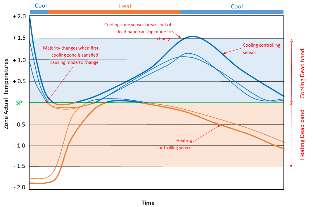
An Auto Mode Dead Band is applied to prevent frequent mode changes. This setting can be adjusted via the iZone AC unit configuration settings.
It is recommended to set the dead band to approximately ±1.5°C from the set point (SP ±1.5°C) for optimal comfort and system efficiency.This prevents the system from ‘hunting’
Preventing Mode 'Hunting' (Auto Mode Logic)
To prevent the system from constantly switching between cooling and heating (a condition known as "hunting"), the iZone system uses a majority-based control strategy when operating in Auto mode with "Zones" as the control source.
How It Works:
- The system will operate in Cooling or Heating based on the majority of Climate zones requesting that mode.
- If the majority shifts from one mode to another, the system will only switch modes when at least one zone in the new majority has exceeded the Auto mode dead band.
- If there is no clear majority (equal number of zones requesting cooling and heating), the system will continue operating in the previous mode.
- When zones not aligned with the current mode detect supply air in the opposite temperature range (via the CDTS sensor), those zones will close to avoid discomfort.
Example (See diagram below):
-
Initial State:
- 3 zones require cooling
- 2 zones require heating
- The system starts in Cool mode.
- The 2 heating zones close when the CDTS sensor detects cold supply air.
-
Majority Shift:
- One cooling zone reaches its set point and switches to heating.
- Now: 2 zones require cooling, 3 require heating.
- The system switches to Heat mode, provided at least one of the heating zones is outside the dead band.
- The 2 cooling zones now close when the CDTS sensor detects warm supply air.
-
Back to Cooling:
- The heating zones reach their set points.
- All 5 zones now require cooling, but remain within the dead band, so the system stays in Heat mode.
- Once any cooling zone drifts outside the dead band, the system switches back to Cool mode.
- The heating zones close when the CDTS detects cool air.